Performance Measurements
Introduction
Do you know the status of your radio station? Does it perform the way it is supposed to perform?
If you are into weak signal VHF-UHF-microwave work, every dB counts and for EME even more so. I will give some hints, in general terms, on how to evaluate your equipment with respect to on the air performance regarding antenna gain, noise figure, G/T etc. For deeper insight in details please refer to the references.
Some general advices for possible improvements and optimization are also given.
This context became most focused on a EME system utilizing a dish, but a lot of the information is applicable for tropo systems and yagi systems as well.
Many of these aspects have been discussed before in different ways, see Ref. [8]. I hope to gather a lot of that information and thoughts in one place.
Noise
Noise is everywhere! You have thermal noise, man made noise, galactic noise and so on. Most of the time noise is your enemy. But, why not make use of your enemy? You can actually use thermal and galactic noise sources as a calibrated signal generator or to be more exact, calibrated noise sources. For free!
Thermal noise is all around us. Everything with a physical temperature and RF-loss generates thermal noise. That means if you point your antenna at trees with foliage, the antenna will see the thermal noise generated by the lossy foliage. The noise from the foliage will add up to the noise generated by the receiver itself together with other noise sources. Thermal noise is a inherent broadband signal and is measured in dBm/Hz, I.E. power per band width. At an ambient temperature of 290 K (+17 deg. C) the noise power is -174 dBm/Hz. Thermal noise is very predictable and is determined by physical constants and can therefore be used as reference. Another way of expressing the noise level is in Kelvin [K]. It is called noise temperature. The -174 dBm/Hz would correspond to a noise temperature of 290 K. Noise temperatures can simply be added to each other in order to determine the total noise temperature of a system. For example if we have a receiver noise temperature of 75 K, an antenna temperature of 50 K and a loss of 0.1 dB (=6.8 K) from the antenna to the receiver it all sums up to a system noise temperature of 131.8 K.
Galactic noise is generated by stars, galaxies, our own Milky Way and planets. The galactic noise varies with frequency and is most dominant at lower frequencies and gets hard to detect above the UHF range with amateur equipment. One exemption is the noise from our own sun, it can be detected all the way up to mm-waves even with amateur equipment. Another extraterrestrial noise source is the moon. The noise the moon generates is actually thermal noise. Galactic noise is well documented and can be used as reference. Between the extraterrestrial noise sources we only have the background noise coming from "big bang", birth of the universe. This noise level is quite low (about 2.7 K = -194 dBm/Hz) and can be used as a reference for low noise (cold sky). The "cold" areas in the sky are larger than the "hot" areas, especially on UHF and up. This means when using a low gain antenna (=wide beam) the contribution from the "hot" areas to the total noise received is low. Pointing a low gain antenna to the sky we will receive a noise temperature that is close to the background level.
Man made noise is mostly found in urban areas but sneaks further and further out in rural areas with the introduction of all new data communication, BPL, ADSL, computers etc. Man made noise is not predictable and can not be used for any measurements except for mapping your own noise environment.
Other noise sources are lightning and static rain. They are of intermittent nature and are, in most cases, of limited nuisance nor use for higher frequencies.
An deeper insight in noise can be found in Ref. [1], [2], [3], [5] and [6].
Prerequisites
In order to be able to evaluate your station with this method, a few things are needed from your station:
A few assumptions have to be made:
Measurements and calculations
As mentioned above, noise from your surroundings can be measured. By using the natural known noise sources together with the above assumptions some vital parameters of your radio station can be checked.
We will determine
by using the measurement methods below.
Noise figure or receiver noise temperature:
Use a small, low gain, low noise antenna with your pre-amp mounted close to the antenna in order to minimize losses. Good antennas for this measurement would be a W2IMU dual mode horn, or any other low noise horn antenna, for 23 cm and up. For 70 cm a EIA Dual Dipole, standard gain antenna would be a good choice. The knowledge of a well defined noise temperature of the test antenna is the clue to be able to find the receiver noise temperature. The W2IMU horn is said to have a noise temperature of 10-20 K and the EIA Dual Dipole 40-50 K. If we do know this, we only have one unknown variable (pre-amp noise temperature), and the equation can be solved. The antenna noise temperature includes contribution from losses in the antenna, noise temperature of the sky the antenna is looking at and noise from any side lobe of the antenna looking at the ground or any foliage.
Point the antenna up into the sky. Avoid pointing the antenna at houses, trees, the sun etc. when getting the cold sky reading as they all will give excess noise and give false readings. Preferably the sun should be below 20 degrees over the horizon. Make the reference reading on your receiver. Point the antenna at the ground and make your second reading. You shall see a clear increase in receiver noise level when pointing the antenna at the ground. The difference between the both readings in dB is the value you are looking for. This value will be used for the calculations. It is often called the Y-factor.
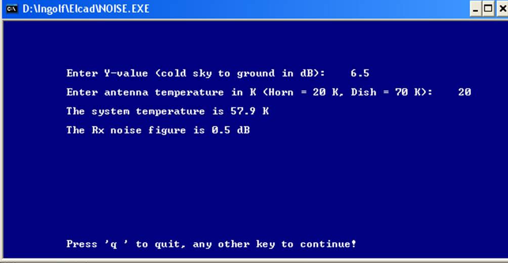
Example: Using a W2IMU dual mode horn you measure a Y-factor of 6.5 dB on 23 cm. A standard antenna temperature of 20 K is used for the W2IMU horn. Insert these figures into the SM6FHZ Noise calculation program (see link below) and you will get a noise figure of 0.5 dB (corresponding to a receiver noise temperature of 35.4 K and a total system noise temperature of 57.9 K). This figure includes the loss from the antenna to the receiver when the measurement was made.
You have now determined your receiver noise temperature. This method is as accurate as or even more accurate than a noise figure meter measurement! This value has an use by it self or as input data for the measurements below. See also Ref. [7].
System noise temperature:
When the receiver noise figure (or receiver noise temperature) has been determined, is is possible to measure the noise temperature for the whole system in order to determine the noise temperature for the main antenna. We used only the horn or any other well known antenna above. The noise temperature of a dish is not well known as we have so many unknown contributions to the total noise temperature (spill over, side lobes, back radiation, reflector leakage, reflector resistive losses etc.). But we can now determine this figure with the data we have from the above measurement. When we know the antenna noise temperature we can judge if any improvements are possible in order to improve our receive performance for extraterrestrial signals.
Use the same procedure as above, point the antenna into the sky first and then down towards the ground. Avoid the same pitfalls as mentioned above. Determine the Y-factor. Use the SM6FHZ Noise calculation program to determine the antenna noise temperature using the receiver noise temperature calculated above.
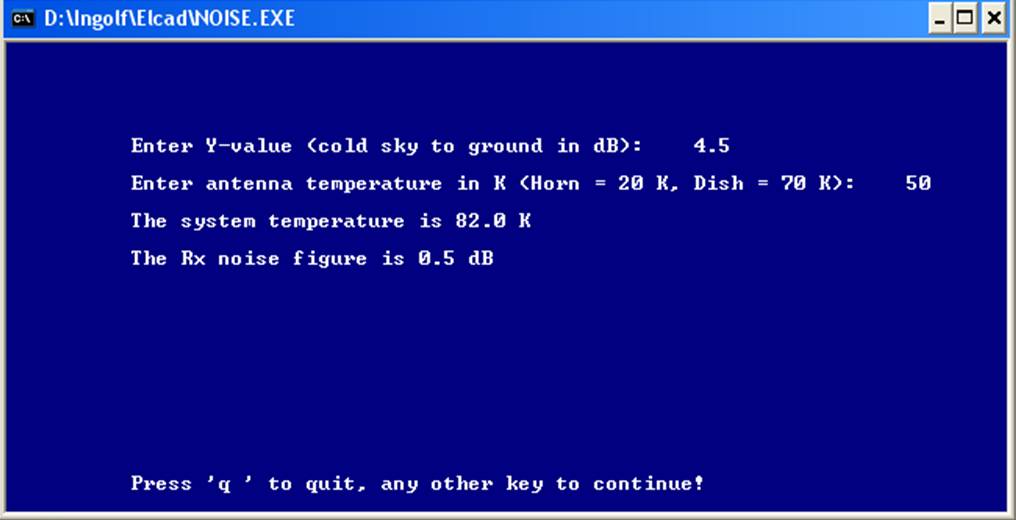
Example: Using your antenna you measure a Y-factor of 4.5 dB on 23 cm. A receiver noise temperature of 35.4 K was determined above. Insert the Y-factor into the SM6FHZ Noise calculation program (see link below) and try different antenna temperature values until you get a noise figure of 0.5 dB (corresponding to a receiver noise temperature of 35.4 K) as the result of the calculation. You will see that 50 K antenna noise temperature will give 0.5 dB NF and a total system noise temperature of 82 K. You have now determined the noise temperature of your antenna. This figure includes the loss from the antenna to the pre-amp when the measurement was done and the contribution from any side and back lobes of the antenna as well as the background radiation from the sky.
You
have now determined the system temperature of your EME system as well
as the antenna noise temperature of your main antenna. This measurement
can of cause be done on a array of yagi antennas as well, as long as
you have determined your receiver noise temperature as described above.
Antenna parameters
The following antenna parameters will be looked into:
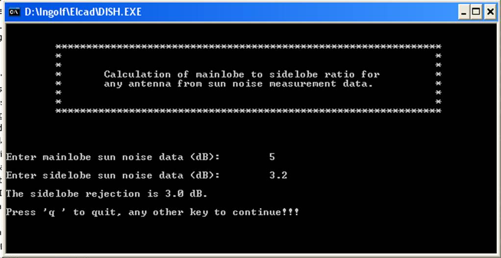
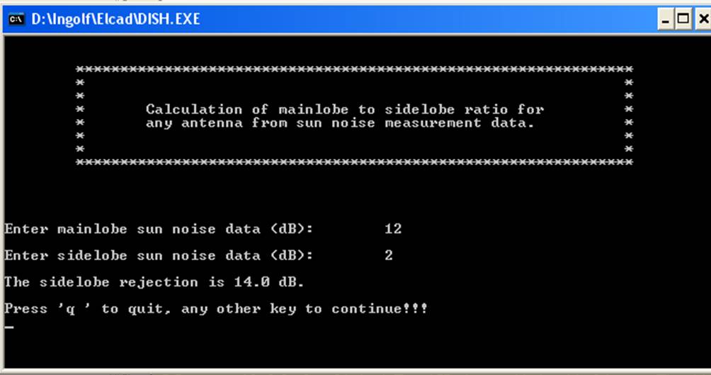
Estimate directivity (D). D [dB] ~10*log(41253 / theta*phi) where theta and phi are the beam width in the E and H-plane of the antenna in degrees. Example: If theta and phi = 3.2 degrees D~36 dBi. In order to get the gain of an antenna you need to take all losses into account. Read more about losses in W1GHZ On Line Antenna Book (see link below). Note, the gain of an antenna will always be lower than the directivity. In order to be able to calculate the estimated directivity measure the beam width in each plane with the aid of the sun. Maximize the sun noise, then offset the antenna to receive 3 dB less power and note the beam pointing in both sides of the main beam in both directions (E and H plane or Az and El). You can use the small program DISH.EXE to calculate where the -3 dB point is in solar noise. This program can be found under the "Tools" headline below. Example 1: If you measure 5 dB sun noise at the beam peak, you shall go down to 3.2 dB sun noise to get to the -3 dB point and read the offset in angle.
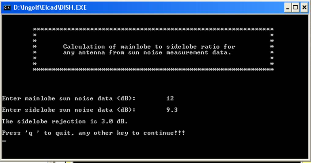
By evaluating the side lobe level of your antenna you can check that the illumination of a dish or the stacking of an array of yagis is correct. If the side lobe level is far from what it should be, something is definitely wrong in the antenna.
Measure sun noise in order to estimate the gain of your antenna. When you know the antenna noise temperature and the system temperature of your station you can estimate the antenna gain by measuring sun noise. Solar flux changes with solar activity so you need to get todays value in order to correctly calculate any parameter from absolute sun noise measurements. The procedure to get the Y-factor (sun noise over cold sky noise) is similar to the above measurements of cold sky to ground and side lobe level. When you have your Y-factor from the sun noise measurement you can put it into DISH.EXE together with the antenna noise temperature (Tant), present solar flux for the band you are measuring and determine the antenna gain.
Example: You measure 14.4 dB of sun noise and have earlier found your antenna noise temperature to be 50 K and your receiver noise figure to be 0.3 dB. Insert 48 for solar flux for 1296 MHz. Actual daily solar flux values can be found on the Internet or by using this function in the VK3UM EME Performance Calculator. Substitute the gain figure until you arrive at your sun noise figure (in this example, 14.4 dB).
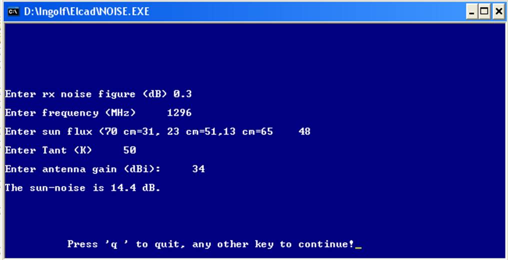
Congratulations! You have estimated your antenna gain to 34 dBi, and that with an reasonable accuracy.
As the solar flux is so variable, the use of other extraterrestrial noise sources can be a way to more reliable antenna gain measurements. Several extraterrestrial noise sources can be found and tracked in the VK3UM EME Planner. More to come on this subject.
How to measure noise in the receiver:
In order to be able to measure the different noise levels needed to make the calculations above we need a method to measure the noise with a sufficient accuracy.
Several methods can be used
Common for all above methods are that the receiver need to be in its linear range for the noise levels involved. Note that broadband noise need more margin to compression than a single carrier in order to maintain linearity. Any automatic gain control (AGC) in the receiver need to be disengaged in some safe way. The larger the noise swing from cold sky to the noise source is the larger demands on linear range in the receiver you get. See also Ref. [6] for more info on measurement methods.
When making the actual measurement, take a reference reading of the noise level in your receiver on your meter with the antenna pointing at a part of the sky where you know you have a "cold" spot. The position of the "cold" spots can be found with the help of the VK3UM EME Planner S/W. Then move the antenna to the noise source you want to compare with (ground, Sun, moon or any other known noise source). Take your second reading. Translate to dB if your readings were taken in linear measure. Calculate the parameters you are interested in as described above.
Accuracy
In all measurements, including the above described, we have a limited accuracy. But, even if the accuracy of the above described measurements is limited, they still will give a very good picture of the performance of your equipment.
Tools
The VK3UM EME Performance Calculator is an excellent and comprehensive tool for evaluating your system. The VK3UM EME Planner is the "standard" EME planning S/W tool. Calculates the position of the moon, the Sun and of a lot of other extraterrestrial noise sources as well as "cold" spots in the sky. A must! They can be downloaded at SM2CEW web site.
SM6FHZ Noise calculation program ( NOISE.EXE, 29 kB) can be used to calculate system noise parameters, conversion between noise figure and noise temperature as well as expected sun noise. This small and simple program runs nicely in an DOS window in both Windows 2000 and XP (have not tried Vista yet).
SM6FHZ Dish calculation program (DISH.EXE, 54kB) can be used to calculate side lobe levels from sun noise measurements, parabolic dish profiles, parabolic dish f/D and estimate the possible gain for a parabolic dish. This small and simple program runs nicely in an DOS window in both Windows 2000 and XP (have not tried Vista yet).
Improvements
EME-systems using an array of yagis can be optimized by using a yagi design with low side and back lobes. The stacking distance will also be a compromise between low side lobes and maximum gain. Optimizing the stacking distance in a yagi array is comparable to choosing a feed to control the edge illumination of a dish. The optimization of losses in the system is also a key factor for a well functioning EME-system. Try to find every part that adds loss and lower it as much as possible, every small loss adds up and the sum will be noticeable.
EME-systems with a dish can be optimized by carefully choosing the feed for optimum performance. Here it is a compromise between gain and low noise. You can optimize for best receive performance, optimum own echoes or for max Tx signal by choosing different feeds. By choosing feed design you can control the illumination of the dish. The illumination of the dish determines if optimized for lowest noise (low edge illumination) or max gain (-10 dB edge illumination). Read more about this in W1GHZ On Line Antenna Book (see link below).
The max gain choice is in most cases not the best choice today, with the very low noise pre-amps available and ample of Tx power. The optimum feed for the best receive performance will be dependent of the Rx NF you have. Different f/D for the dish will need different feed designs and the f/D also gives some limitations to the noise performance. A deep dish (low f/D) will generally give lower noise than a flat dish. Again, optimize for low loss everywhere including cables, relays, connectors etc. See the examples below. Think about how You should optimize Your EME system with respect to dish illumination! There is no obvious or absolute true answer to this question. One extreme would be to optimize for being heard by other stations (max gain to any expense, noise temperature for instance). Another extreme would be to optimize for lowest antenna noise (low antenna temperature to any expense, gain for instance). Note, lowest possible antenna noise is not the same as optimum receive performance. Still another way to optimize would be for maximum own echoes (and that is not the same as hearing other stations as good as possible). But, bear in mind the differences between some of these cases are quite small but still worth considering. You can become phliosophic about this issue, read more here!
Optimizing the antenna for low antenna temperature includes minimizing the resistive losses, minimizing any side lobes and minimizing the spill over including backward radiation.
The noise pick-up of an 50 MHz antenna can be improved by making the radiation pattern as clean as possible. Especially galactic noise can be fought by minimizing the upward and backward radiation of the antenna. If you are pointing directly at the noise source there is not much to be done about it, but try to minimize noise pick-up from other directions. A narrow main beam will also help to reduce noise pick-up close to the wanted direction. There are several dB's in receive performance to be found.
Brief understanding of the importance of the last tenth of a dB
When coming to very low NF and antenna noise temperatures you will not gain dB by dB or tenth of a dB by tenth of a dB, you will gain MUCH more! You get easily fouled by the dB as it is not a absolute measure nor is it a linear measure. The dB is a relative measure and it is logarithmic. If you use noise temperature as the measure when you make the comparison of a improvement, you will get a much better feeling of how much you actually improve. Here are a few examples of how much you gain by certain improvements;
In an tropo system when going from 3 dB receiver total NF to 2 dB receiver total NF with an antenna temperature of 290 K you will gain: 3 dB NF = 288.6 K => system temperature = 288.6 + 290 = 578.6 K, 2 dB NF = 169.6 K => system temperature = 169.6 + 290 = 459.6 K. Difference is 10log (578.6 / 459.6) = 1.0 dB improvement.
In an EME system when going from 3 dB receiver total NF to 2 dB receiver total NF with an antenna temperature of 75 K you will gain: 3 dB NF = 288.6 K => system temperature = 288.6 + 75 = 363.6 K, 2 dB NF = 169.6 K => system temperature = 169.6 + 75 = 244.6 K. Difference is 10log (363.6 / 244.6) = 1.7 dB improvement.
In an EME system when going from 0.5 dB receiver total NF to 0.2 dB receiver total NF with an antenna temperature of 30 K you will gain: 0.5 dB NF = 35.4 K => system temperature =35.4 + 30 = 65.4 K, 0.2 dB NF = 13.7 K => system temperature = 13.7 + 30 = 43.7 K. Difference is 10log (65.4 / 43.7) = 1.75 dB improvement.
In an EME system when going from 0.2 dB receiver total NF to 0.1 dB receiver total NF with an antenna temperature of 20 K you will gain: 0.2 dB NF = 13.7 K => system temperature =13.7 + 20 = 33.7 K, 0.1 dB NF = 6.8 K => system temperature = 6.8 + 20 = 26.8 K. Difference is 10log (33.7 / 26.8) = 0.99 dB improvement.Links
The following links will give more info about noise and noise sources as well as measurement techniques and antennas.
VK3UM EME Planner and VK3UM EME Performance Calculator can found at SM2CEW web site
References
[1] IEEE TRANSACTIONS ON ANTENNAS AND PROPAGATION. VOL. AP-32, NO. 7, JULY 1984, Natural Radio Noise—A Mini-Review, WARREN L. FLOCK, AND ERNEST K. SMITH.
[2] VHF COMMUNICATIONS -1988, Radio Astronomy for the VHF/UHF Radio Amateur, Hans J. Hartfuss, DL2MDQ.
[3] VHF COMMUNICATIONS -1/1984, Determining the Parameters of a Receive System in Conjunction with cosmic Radio sources, Dragoslav Dobridic, YU1AW.
[4] IEEE TRANSACTIONS ON ANTENNAS AND PROPAGATION. VOL. 45. NO. 7, JULY 1997, G/T Maximization of a Paraboloidal Reflector Fed by a Dipole-Disk Antenna with Ring by Using the Multiple-Reflection Approach and the Moment Method, Per-Simon Kildal, Svein A. Skyttemyr, and Ahmed A. Kishk.
[5] RECOMMENDATION ITU-R P.372-8 Radio noise
(You can get it at GM3SEK's WEB-page http://www.ifwtech.co.uk/
[6] SUNNOISE MEASUREMENTS, Doug McArthur, VK3UM, GippsTech 2008, Sunnoise_Measurements.pdf, (362 kB)
[7] DUBUS 1/1994, Noise Figure Measurement on 1.3 GHz and 432 MHz using standard antennas, Hannes Fasching, OE5JFL
[8] DUBUS 3/1992, Performance Evaluation for EME Systems, Reiner Bartelsmeier, DJ9BV and Patrick Magnin, F6HYE
This
page is under development and the links may not work as expected. The
content of the text will also be updated. Check again soon and they can
be updated!
Updated September 14, 2009. http://www.2ingandlin.se/SM6FHZ.htm